One of the topics in my HPLC Troubleshooting: A Performance Qualification Approach Master Class is the importance of knowing how your HPLC system works when it is working correctly. Knowing the normal detector noise and drift can help you to realize when there is a problem, by giving you a reference value for your detector in addition to the detector specifications provided by the manufacturer.
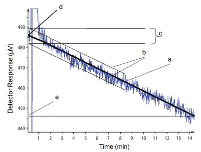
The setup is quite simple. Remove the column, replace it with a piece of connecting tubing (e.g., 1 m x 0.125 mm) and replace the mobile phase with HPLC-grade water. Set the detector conditions to those listed in the specifications. In the present case, we’re looking at an ultra-violet (UV) detector and the specifications are listed for 255 nm, so the wavelength is set at 255 nm. Run the flow rate at 1 mL/min and allow the detector to warm up. After a steady baseline has been established, turn up the amplification so that the deviations of the baseline are clearly visible, as seen in Figure 1. Collect about 15 min of baseline and either print it out or work on the computer monitor.
 Figure 1
Start by drawing a best-fit straight line through the baseline as in (a) of Figure 1; this will be used to measure the detector drift. Determine the noise by drawing lines parallel to the baseline, trying to capture most of the small excursions from the baseline as in (b) of Figure 1.The magnitude of the noise signal is measured as the vertical distance between the two noise lines (Figure 1c). Note this value and convert it to the units of measure listed in the detector specification. In the present case, we’re looking at noise from a UV detector, so the units are absorbance units (AU). So in our case:
(490 µV – 482 µV) x (1 mV / 1000 µV) x (1 V / 1000 mV) x (1 AU / V) = 8 x 10⁻⁶ AU
The observed value should be within five times the detector specification. This allows for some aging of the lamp as well as the non-ideal conditions in the laboratory as compared to the manufacturer’s test facility. In the present case, the specification was 5 x 10⁻⁶ AU, so the noise is within specification.
Drift is calculated in a similar way – just measure the offset between points on the best-fit line over a fixed period – 15 min is recommended – as in Figure 1d and e. Convert this to the appropriate units:
((486 µV – 446 µV) / 15 min) x (1 hr / 60 min) x (1 mv / 1000 µV) x (1 V / 1000 mV) x (1 AU / V) = 1.6 x 10⁻⁴AU / hr
As with noise, the drift should be within five times the specification. The present detector had a specification of 1 x 10⁻⁴ AU / hr, so this test passes also.
In future HPLC Solutions , we’ll look at some different types of noise and their sources. For drift, the most common causes are insufficient warm-up of the detector and thermal drift. First, repeat the test to see if it is any better after the detector has been allowed to warm up for at least 1 hr. If the drift persists, look for sources of temperature variation. For example, make sure the tubing connecting the injector and detector are routed through the column oven and that the oven is operating (e.g., 30 ⁰C). If the tubing from the column oven to the detector is exposed, insert it in an insulating sleeve, such as a piece of thick-walled plastic or rubber tubing. Are any air vents blowing on the system? It may be necessary to redirect the airflow or shield the detector from temperature fluctuations.
This blog article series is produced in collaboration with John Dolan, best known as one of the world’s foremost HPLC troubleshooting authorities. He is also known for his research with Lloyd Snyder, which resulted in more than 100 technical publications and three books. If you have any questions about this article send them to TechTips@sepscience.com
