Under discussion is one of the newer approaches to capillary column backflush: the uncoated pre-column configuration.
Uncoated (but deactivated) capillary columns are often intimately connected to analytical columns with glass press-fit connectors or metal straight unions. Originally, such pre-columns were found to help overcome some of the problems found in capillary GC with condensed sample at the head of the column. Such can happen in splitless injections, where even though the sample is vaporized in the inlet, it recondenses in the head of the column. This is also the case when injecting samples with cool on-column injection where the sample is introduced directly into the column as a liquid.
In these cases, the condensed solvent can spread out over a long zone, which in turn creates a wide initial band width for solute peaks. In the extreme cases when the solvent is not very miscible with the stationary phase (polarity incompatibility), the solvent zone can break apart into many separate zones, which then causes solute peaks to be “split” or show a “Bart Simpson”, as I call it (spiked hair look, doh!).
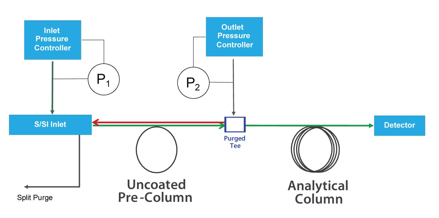
 Figure 1: A typical uncoated pre-column backflush configuration. A simple inert purged tee with programmable pressure controller is placed between the pre-column and the analytical column. Once the last peak of interest has passed the purged union (approximately 150 oC below elution temperature from analytical column), inlet pressure is decreased so that flow through the pre-column reverses and unwanted sample components are backflushed.
It was found that an uncoated pre-column corrected these phenomena through stationary phase focusing at the head of the analytical column (see references within reference 1 below). Because the pre-column has no stationary phase, solutes will start to evaporate and migrate out of the column at low temperatures. When the wide migrating bands reach the front of the coated column, they are retained and focused, thereby significantly reducing band width and recombining split peaks.
What is not well appreciated is that even though there is little retention in these uncoated columns, there is still some. In fact, there is enough retention of high-boilers (late eluting compounds) that we can make good use of it for backflush. In the same configuration discussed last month for coated pre-columns, an uncoated pre-column can be inserted ahead of the analytical column, as illustrated in Figure 1.
There are many reasons why I prefer uncoated pre-column backflush compared with the other two modes (post-column and coated pre-column). These are listed below.
- Large differential in elution temperature from pre-column versus analytical column improves replication on multiple systems/locations; it is a more repeatable solution.
- Sample components are transferred to the analytical column at low temperatures and are focused by the stationary phase of the analytical column, decoupling retention of the two sections (resulting in more rugged conditions). - Components are backflushed more quickly (at lower temperatures and/or with fewer column void volumes), making this the fastest backflush technique (often components are completely backflushed within seconds).
- Fastest backflush mode, concurrent with ongoing analysis, so when the last compound of interest has eluted from the analytical column, the run can immediately stop and prepare for the next analysis (minimizing cycle time) - Analytical separation conditions can be exactly the same as an original method that used no pre-column.
- Column mass flow is determined by the pressure at the purged connection device and it can be set to be exactly the same as the original method.
- The pre-column has no influence on the elution time/temperature from the analytical column. This is not the case with coated pre-columns wherein the pre-column does influence overall retention times. - Flow to detectors during backflush is the least of all backflush configurations – exactly the same as original method.
- One has considerable flexibility in choice of pre-column dimensions (especially i.d.) and flow rates (as long as the pre-column flow does not exceed 95% or so of the analytical column flow).
- Retained matrix has least influence on initial peak shapes and retention times.
- Cheapest pre-column to replace when necessary.
- Easiest and most accurate replication of retention time locking methods. This is an Agilent Technologies approach to matching analyte retention times across systems and over time (Agilent website).
Nothing is perfect, though, and there are of some key situations when uncoated pre-column backflush mode is not the best choice.
- Uncoated pre-column backflush can only be used with temperature programmed analyses spanning over 100 °C, or so.
- It cannot be used with pressure pulse injections.
- It is not as inert as a coated pre-column, so may not be suitable for very active compounds or for moderately active compounds at trace levels.
- Backflush timing is more difficult to determine than if using a post-column approach (but easier than coated pre-column approach).
- Peaks eluting from an uncoated pre-column are wider peaks than with coated column approach.
- Elution temperatures from the pre-column are dependent on sample amount and sample matrix.

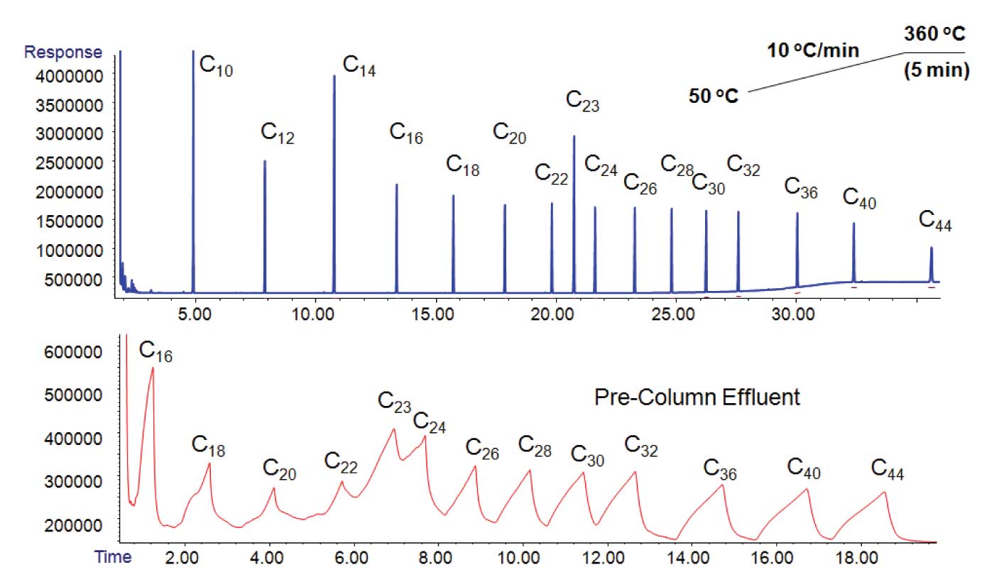
Figure 2: Comparison of elution profiles of an n-alkane standard from an uncoated pre-column (bottom) and the analytical column (top) attached to it. 1 m X 250 μm uncoated but deactivated fused silica tubing attached to a 29 m x 250 μm x 0.25 μm DB-5MS column. (reprinted from Agilent Technologies, Inc., with permission)
Figure 2 compares the shapes and widths of peaks eluting from an uncoated pre-column and then from an analytical column following it. Notice that the peaks from pre-column are misshapen and wide. It is clear from the narrowness and symmetry of the peaks eluting from the analytical column that stationary phase focusing is quite effective.
The width of the peaks eluting from an uncoated column are so wide because there is so little capacity for retention in the column. There is a combination of overload, surface adsorption, and co-solvation/interaction effects. It is not unusual for peaks elution widths to span over 1 min. This is why uncoated pre-column backflush will never be able to precisely cut between neighboring peaks. In addition, elution temperature is dependent on sample load, injected volume and overall sample composition. The positive side is that timing backflush precisely between neighboring peaks is usually not important; the important need is to remove the much more highly retained components and end the run as soon as possible. Uncoated pre-columns can do this quite nicely.
Looking at Figure 2 more carefully, one can see that the earliest discernable retained peak is n-C16. Uncoated pre-columns are certainly not the best choice for samples of volatile compounds; a coated pre-column or post-column backflush configuration would be better choices. In general, one can see that the compounds in this example elute approximately 150 °C earlier than they elute from the analytical column. Elution temperature differential is a function of phase ratio of the analytical column (thicker films, lower phase ratio increases the differential) and reduced ramp rate (higher °C/tM increases the differential)[1].

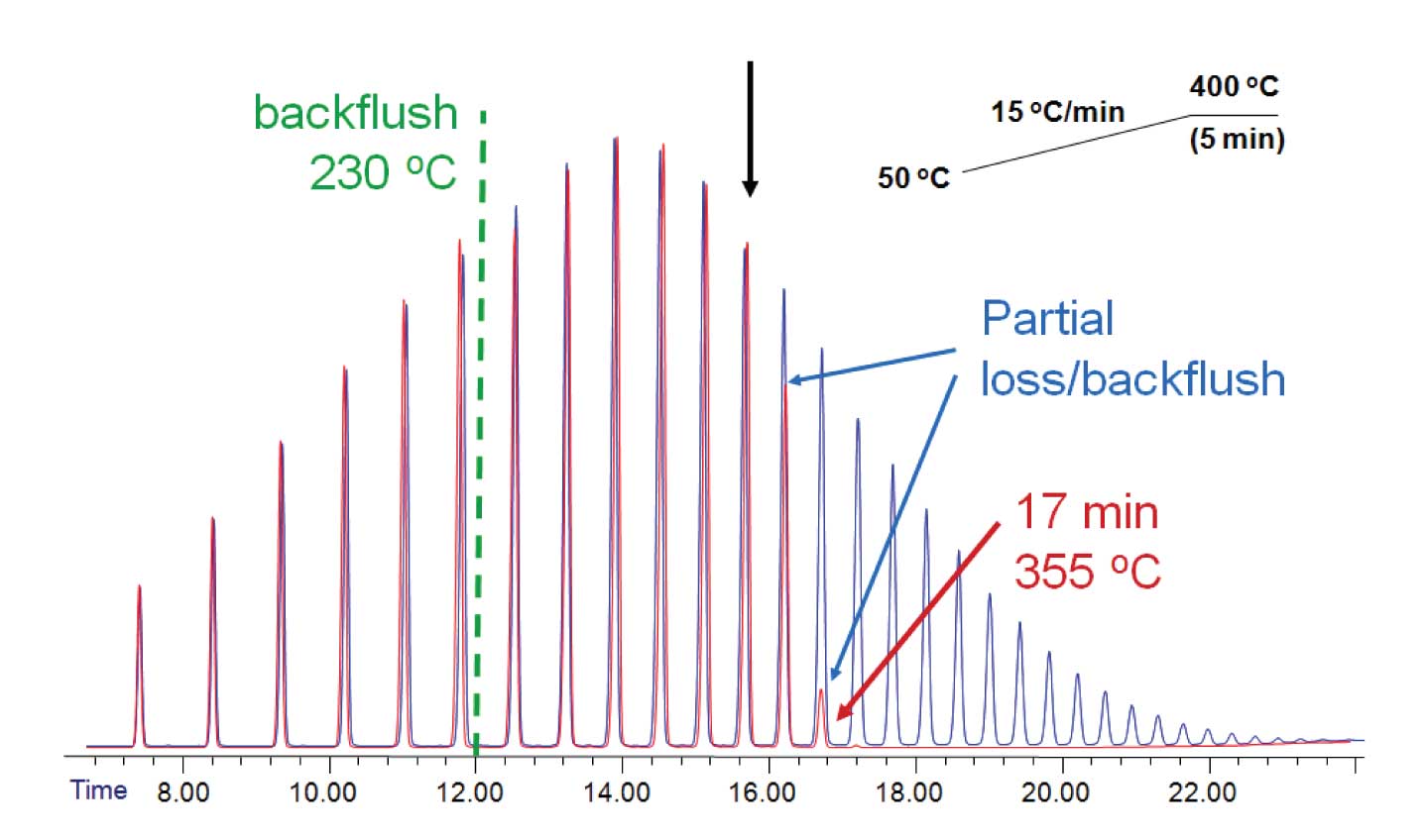
Figure 3: Comparison of original and backflushed chromatograms for simulated distillation calibration. The uncoated pre-column in this example is a high temperature coated metal column: Pro Steel deactivated tubing (Agilent Technologies) 1 m x 530 μm. In= back PTV Inlet (He carrier gas), out = Aux EPC 1. Forward flow holdup time = 0.022726 min. Flow program blue (no backflush): 10 mL/min for duration of the run. Flow program (red, backflush): 10 mL/min for 12 min then -99 mL/min per min ramp to -44.288 mL/min for remainder of the run. Analytical column: 5 m x 530 μm x 0.15 μm DB-HT Sim Dis (Agilent Technologies). In = Aux EPC 1, out = FID. Flow 12 mL/min, constant flow mode. (reprinted from Agilent Technologies, Inc., with permission)
In an example in Figure 3, one can see a simulated distillation calibration using n-alkanes, with and without backflush. With an uncoated pre-column backflush starting at 12 min and analysis continuing concurrently in the second column, one can see that the peaks up to 16 min are quantitatively transferred to the analytical column (same peak heights as the original). The next three peaks are successively reduced in height. This is the manifestation of the overlap of those peaks as they were eluting from the pre-column. All peaks that had eluted from the second column after 17.5 min were totally excluded from the analytical column and effectively backflushed. In a real run with this type of backflush, the run could then have been stopped at 17.5 min, cool down of the oven could have started, and cycle times would be minimized.
In the example of Figure 3, the elution temperature differential between the pre-column and the analytical column is only about 65 °C. This is because the analytical column has such a high phase ratio (883 versus 250 for the example in Figure 2).
Setup and Optimization
I suggest selecting a pre-column that is either the same diameter or one size larger than the analytical column. I suggest using a length of 2-3 m. Shorter lengths might work, but there can be some bleed through to the analytical column for certain solvents and sample loads, so 2-3 m is fairly safe. Excessive lengths (i.e., > 3 m) don’t provide a benefit and can increase sample losses for active compounds.
If analysing polar or labile compounds, you may have to screen columns from various vendors to find the most inert for your sample type. Unfortunately, few vendors provide useful inertness information about their deactivated tubing, so you have to do the work and hope they don’t change processes down the road. As mentioned before, if you have samples with very labile/active compounds, especially at trace levels, you might be better served using a coated pre-column backflush mode in the first place.
To set up an uncoated pre-column configuration, the procedure is basically the same as with coated pre-columns. The pre-column is attached to an inlet and its outlet is connected to a purged connector (many styles are available from several vendors). I favor simple devices such as a purged tee with minimal internal surface area to which sample would be exposed. I prefer soft metal Siltite® ferrules (polymeric ferrules such as Vespel® interact with samples) for column connections, and suggest you select a device that has been deactivated with something effective (e.g., Siltek). Pressure control is best provided by an electronic pneumatic device as illustrated in Figure 1, although other approaches can be made to work.
As with the coated pre-column, pressures/flows are set from the detector end toward the inlet. So first, set device pressure to match the pressure/flow conditions of the original method. Using this pressure as the outlet pressure of the pre-column, set inlet pressure to provide no more than 90% of the flow of the analytical column (to provide a buffer for inaccuracies in column dimensions). If the analytical column is run in constant flow mode, then the pre-column should be run in constant flow mode. If there is a pressure or flow program, then the pre-column should have an analogous pressure or flow program such that its flow never exceeds 90% of the analytical column flow.
To determine a suitable backflush time, I recommend that you start
125 °C below the elution temperature of the peak from the analytical column (assumes an average phase ratio of 500). So if the last compound of interest elutes at 250 °C from the analytical column, then the pre-column backflush should start at 125 °C. The goal of rugged backflush timing is to ensure that 100 % of the last compound of interest is recovered (passes the purged junction) with some safety margin (err on the high side). Remember that there will also be some bleed through of neighboring peaks that are more highly retained (as seen in Figure 3), but that is usually of no concern.
If the last peak of interest is partially backflushed in the initial screening run, then start the backflush 25 °C lower and re-evaluate. If too many later eluting neighbors are fully recovered, then re-evaluate with a backflush starting 25 °C higher. Fine tune timing in 10 then 5 °C increments, if necessary. If you are fortunate enough to have a standard with the last compound of interest plus a few extra peaks eluting close to it, then the optimization process is straightforward.
Reference
1. Matthew S. Klee, “Gas chromatographic retention in uncoated fused silica capillaries”, J. Sep. Sci. , 32 (2009) 3133 – 3143
® SilTite is a registered trademark of SGE Analytical Science Pty Ltd.
® Vespel is a registered trademark of E. I. Du Pont de Nemours and Company Corporation
This blog article series is produced in collaboration with Dr Matthew S. Klee, internationally recognized for contributions to the theory and practice of gas chromatography. His experience in chemical, pharmaceutical and instrument companies spans over 30 years. During this time, Dr Klee’s work has focused on elucidation and practical demonstration of the many processes involved with GC analysis, with the ultimate goal of improving the ease of use of GC systems, ruggedness of methods and overall quality of results. If you have any questions about this article send them to techtips@sepscience.com


