A reader asks, I would like to split HPLC column effluent between an evaporative light scattering detector (ELSD) and a fraction collector. What is the best way of doing this, particularly as we may want a biased split, i.e., 10% to detector and 90% to fraction collector?”
Splitting the column effluent between a detector and another device is a common technique if you want to isolate a peak for purification or structural elucidation. This is especially true if the detector modifies or destroys the peak during the detection process, as is the case for the ELSD, charged aerosol detector (CAD), or mass spectrometric detector (MS).
Splitters fall into two categories, commercially available and home-made. Several companies make splitters that you can purchase. For example, I did a Google search on “HPLC splitter” and the first hit was Analytical Scientific Instruments (ASI, http://www.hplc-asi.com/products/flow_splitters/index.htm), with six types of splitters illustrated on their splitter page. These include two-stream (binary), three- and four-stream (multi-port) splitters with fixed split ratios, as well as adjustable splitters. Adjustable splitters generally use a metering valve, such as a needle valve, to control the flow of one of the streams and thus control the split ratio. Commercial flow splitters work well, and the adjustable ones are especially attractive if you have a situation where you may need to change the split ratio often for different applications.
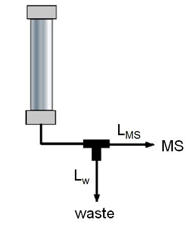
On the other hand, you can make a simple splitter with a PEEK tee (e.g., Upchurch/IDEX part P-727, http://webstore.idex-hs.com/Products/specsheet.asp?vSpecSheet=386&vPart=P-742) and two pieces of PEEK tubing. Such a splitter is illustrated in Figure 1. Although there are formulae in text books on how to determine the length of the two outlet tubes based on the diameter and desired flow split, I find it easiest to use a empirical approach, because a formula-based determination usually will still require fine-tuning to compensate for minor nuances of the system.
Here’s how I go about it. Connect the tee to the end of the column as shown Figure 1 so that the straight-through passage leads to the detector. Then connect the detector to the tee. Now measure the length of the tubing between the outlet of the splitter and the detector. For example, in Figure 1, the splitter is to be used in an LC-MS, so I would include the length of tubing plus the length of the spray tube in the electrospray interface (LMS in Figure 1).

Figure 1
Now use this length to estimate the length of tubing needed on the side-arm tube (to waste, LW, in Figure 1) to obtain the desired split ratio. Let’s say you want a 1:1 split and there are 39 cm of tubing from the tee to the tip of the ESI spray tube. This means that you estimate 39 cm of tubing also will be needed on the waste arm. I start with about 25% more tubing on the side arm than I think I need, then adjust it based on flow measurements. This is because other sources of flow resistance also will affect the split ratio, and it is easier to shorten a piece of PEEK tubing than lengthen it. So in this case, I’d start with ≈50 cm of PEEK tubing for LW. Then measure the split ratio and adjust LW until the desired split is obtained. For example, if the flow rate from the column is 0.4 mL/min and you measure 0.1 mL/min from LW, the flow is too low, meaning there is too much resistance in LW. Trim off a few cm of the waste tube and re-measure; continue until you get a flow of ≈ 0.2 mL/min from LW. With a little practice, you’ll be able to more closely estimate the tube lengths to get the desired split ratio. Usually an approximate split ratio will be adequate. So if you want a 1:1 split, it is unlikely that a ±10% deviation from this will cause any problems.
One thing I like about home-made splitters is that they are inexpensive and easy to make. So I tend to make one for each application, then I can label them and use them only for that application, rather than trying to adjust the split each time I change from one method to another.
This blog article series is produced in collaboration with John Dolan, best known as one of the world’s foremost HPLC troubleshooting authorities. He is also known for his research with Lloyd Snyder, which resulted in more than 100 technical publications and three books. If you have any questions about this article send them to TechTips@sepscience.com
